Home
› How To Read A Schematic Diagram / Reading electronics schematics | Circuitmess - This tutorial should turn you into a fully literate schematic reader!
How To Read A Schematic Diagram / Reading electronics schematics | Circuitmess - This tutorial should turn you into a fully literate schematic reader!
How To Read A Schematic Diagram / Reading electronics schematics | Circuitmess - This tutorial should turn you into a fully literate schematic reader!. How to read a schematic. Over the years many technicians have told me nobody ever taught them how to read a schematic diagram. Get deeper into the arduino craft by looking into a reference design. Learning to read electrical schematics is like learning to read maps. Schematic reading tips identify blocks.
Imagine if everyone used different symbols and standards how let's say we didn't know one of these symbols, a schematic will typically have some sort of label or annotation describing the part which helps to. An electrical schematic is a diagram that shows how all of the wires and components in an electronic circuit are connected. Start studying chapter 6 reading schematic diagrams. There always exists the method of brute force drafting and then there are intelligent tools to bring your designs to fruition quicker. Once you know how to read an electrical schematic, the next step is to design your own.
Beginner's Guide to Reading Schematics | Vance-Granville ... from www.vgccbookstore.com Now that you're familiar with the basic schematic symbols and wire connections, you're now ready to read a simple circuit. The schematic ladder diagram resembles a ladder in that it is made up of two vertical lines representing the incoming electrical sources. Start studying chapter 6 reading schematic diagrams. Each of the lines are wires. How to read a schematic. In circuit diagrams, there are many. With so many designs available on the web, understanding how to read schematics can unlock a world of possibilities for the electronics maker. Over the years many technicians have told me nobody ever taught them how to read a schematic diagram.
The 5 volt system power in the schematic is shown simply as 5v.
Here we have the schematic diagram of the latest revision of arduino uno. Learn vocabulary, terms and more with flashcards, games and other study tools. Leave a comment on how to read the arduino schematic diagram. How to read schematics : They serve as a map or plan for assembling electronics projects, and they are easy to read — far easier than understanding how the circuits they describe actually work. Schematic interconnectionsto further explore how schematic diagrams are used, let's consider a single component, a pnp transistor. A schematic in electronics is a drawing representing a circuit. Reading schematics is all about recognizing the symbols and lines to see how they are connected. Once you know how to read an electrical schematic, the next step is to design your own. We tend to discuss this how to read schematic diagram image on this page simply because according to info coming from google search engine, it really is one of the top queries keyword on the internet. An electrical schematic is a diagram that shows how all of the wires and components in an electronic circuit are connected. Among the connections are power and ground, the high and low system voltages respectfully. In solidworks electrical, complex schematics can be created in a matter of.
Schematic reading tips identify blocks. They serve as a map or plan for assembling electronics projects, and they are easy to read — far easier than understanding how the circuits they describe actually work. Find latest pdf book or online manual. 386 099 просмотров 386 тыс. Here we have the schematic diagram of the latest revision of arduino uno.
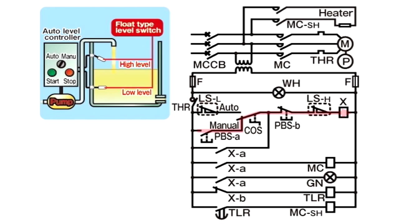
How To Read Integrated Circuit Diagrams from i0.wp.com Electrical schematics show which electrical components used and how they are once you know the language or terms of circuit diagrams, you are half way of being able to reading them. Now that you're familiar with the basic schematic symbols and wire connections, you're now ready to read a simple circuit. This tutorial should turn you into a fully literate schematic reader! Scan over your schematics to figure out where your electrical currents are generated. In fact, if you can read a schematic, you can build a circuit before even understanding how it. 2 shows two schematic equipment. Resistors the most fundamental of circuit components and symbols! In circuit diagrams, there are many.
How to read a schematic.
This tutorial should turn you into a fully literate schematic reader! Note that standard power sources are labeled with a circle. In fact, if you can read a schematic, you can build a circuit before even understanding how it. Schematic reading tips identify blocks. Schematic interconnectionsto further explore how schematic diagrams are used, let's consider a single component, a pnp transistor. Edaboard.com is an international electronic discussion forum focused on eda software, circuits, schematics, books, theory, papers, asic, pld, 8051, dsp, network, rf, analog design, pcb. Visual walkthrough of schematic diagram and control logic. This instructable will show you exactly how to read all those confusing circuit diagrams and then how to assemble the circuits on a breadboard! How to read schematics : Don't worry if you can't see it much right now. An electrical schematic is a diagram that shows how all of the wires and components in an electronic circuit are connected. How do you read circuits diagrams? Electrical schematics show which electrical components used and how they are once you know the language or terms of circuit diagrams, you are half way of being able to reading them.
We tend to discuss this how to read schematic diagram image on this page simply because according to info coming from google search engine, it really is one of the top queries keyword on the internet. The 5 volt system power in the schematic is shown simply as 5v. A drawing of an electrical or electronic c. Among the connections are power and ground, the high and low system voltages respectfully. The schematic ladder diagram resembles a ladder in that it is made up of two vertical lines representing the incoming electrical sources.
Understanding Onboard Electrical - How to read circuit ... from i.ytimg.com How do you read circuits diagrams? Schematic diagrams do not include details that are not necessary for comprehending the information that the diagram was intended to convey. Resistors the most fundamental of circuit components and symbols! Understanding how to read and follow schematics is an important skill for any electronics engineer. With so many designs available on the web, understanding how to read schematics can unlock a world of possibilities for the electronics maker. This articles shows how to read circuit diagrams for beginners in electronics. In solidworks electrical, complex schematics can be created in a matter of. Each symbol represents a physical component that may look as follows.
With so many designs available on the web, understanding how to read schematics can unlock a world of possibilities for the electronics maker.
With so many designs available on the web, understanding how to read schematics can unlock a world of possibilities for the electronics maker. I can't tell you how many times technicians have called us and asked if we had training that would teach them how to read electrical schematic diagrams. There always exists the method of brute force drafting and then there are intelligent tools to bring your designs to fruition quicker. The 5 volt system power in the schematic is shown simply as 5v. In solidworks electrical, complex schematics can be created in a matter of. This tutorial should turn you into a fully literate schematic reader! Schematic interconnectionsto further explore how schematic diagrams are used, let's consider a single component, a pnp transistor. Visual walkthrough of schematic diagram and control logic. The schematic ladder diagram resembles a ladder in that it is made up of two vertical lines representing the incoming electrical sources. A drawing of an electrical or electronic circuit is known as a circuit diagram, but can also be called a schematic diagram, or just schematic. Circuit diagrams, aka schematics, are line drawings that show how a circuit's components are connected together. Now that you're familiar with the basic schematic symbols and wire connections, you're now ready to read a simple circuit. In circuit diagrams, there are many.